

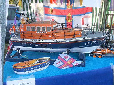
Mersey Class Lifeboat 1/12th Scale

By Gregg 93 entries 10 Feb 2012 — 3 Dec 2016
16Likes
85Comments
Chapter 62 / 93

93 chapters · Page 7 of 10

Gregg #62 of 93 1

Trim tabs.

I constructed the trim tabs from plasticard, using 2mm for the base main plate and thinner section for the upper bracing pieces and hinge plates. Although I have made them complete with hinges, the actuating cylinders on my build are fixed position and non adjustable for trim. I have set these to run at 0 degree trim. After a bit of fiddling I found that this setup was better suited for this hull/build. Setting at 2 it lifted the stern up too high at speed and created too much prop wash as it was lifting the props out of the water and at -2 the stern ran too low and almost washed over the stern deck.
It is possible to make the trim tabs operable by using through rods, which pass through the cylinder outer tubes, and then "pivot" on a see saw just under the stern deck, then run inside and link up to a servo arm. [see model boats mag may/june 2004].
Gregg #63 of 93 1

Flying bridge mast.

One of the Iconic items of the boat, but the majority of the parts easy to replicate. You do have 2 choices here, either build in brass and make it super strong [but heavy], or build in plastic, for lightness, but have some flexibility to take the odd knock or bump.
I opted for plastic, plasticard and tube to be exact. The main base plates are flat plasticard, with additional reinforcing strips. There are 2 hollow tubes which run either side [in sections] these are the cable trunks on the full size and WILL be the same on the model, as I can use them to run the power cables for the navigation lights, radar motor, beacon and stern spot lamp too, so watch on the sizes of tubes you use, to allow for all the cables. I managed to narrow the cables down to a total of 6, 3 run down one side and 3 in the other, I ran double earth cables due to the small sizes of cables used, to allow for the power useage. I decided being as I was using plastI for the build, NOT to make the mast so it lowers and hinges, it runs the risk of breakage with the numerous demonstrations of such, so will run always in "at sea" condition [fully rigged].
Gregg #64 of 93 1

Radar.

I wanted to make the radar rotate, but also wanted to make it so the motor or the radar head's drive could not be seen, so mounting the motor below deck and running a thin driveshaft up through the deck, to the radar head was not possible as it would look ugly and interfere with the positioning of the deck figures [crew] later on. So I managed to source a nice metal geared micro motor, small enough in height to fit inside the actual "scale" radar motor case, The motor is rated at 3v, and more Importantly, gives a mere 30rpm speed output, exactly the speed listed in the details of the radar system fitted to the real boat. As noted in previous update, the wiring runs down inside the cable trunking, so this is not seen either.
Gregg #65 of 93 1

Radar pt2

I have now made up the radar motor box and installed the motor, in to the box "from below" the output shaft is the only thing visible from the outside. I did remember to lightly oil the gearing before "encasement". The motor is rated at 3v and 30 rpm, just right for a JRC unit.

The compnay I buy these micro motors from do many other bigger AND SMALLER types,with either nylon gears or metal, nylon shafts or metal versions and wel worth a look see. Ok, so means international shipping, but they turn an order round in 2 -3 weeks.
http://www.gizmoszone.com/shopping/agora.cgi
Gregg #66 of 93 1

Wiring up the mast head

Now that the radar motor assembly has been installe don the mainmast, I can now feed the wiring up through the cable trunk pipes, up in to the "box" behind the radar motor. This is where all the joins will be made to/from all the lights and radar motor. I like to use as many different coloured cables as possible and make a note of the colours used for what item too, so tracing a fault [in the unlikely event of....] is made easier and less hassle too.
Once all the lights had been tested, the cables were cut to length and heat shrink tube put over all the joints and the lid glued over the cable box to keep it watertight.
Gregg #67 of 93 1

Df Aerial

Now that the electrics to /from the mast are complete and sealed up, I can now add the Df aerial assembly and the rear bracket for the blue beacon lamp, amber "flood alert lamp" and stern spotlamp.

The aerial tube is a piece of brass tube and the upper aerial is plastic rod, bonded through a lfat circular plastic disc, with a piece of thicker plastic rod, passed through the centre of the disc, so it neatly drops in to the brass tube, but is removeable if necessary for transit to/from the pool site.
Gregg #68 of 93 1

Support arm.

This arm, taken as a template off the plans and resized was easy enough to create from some hollow plastruct tubing, using plasticweld to join all the angled bits together. I did allow some "extra depth" on the 3 end pieces, so they pass through a flat collar plate, where they meet the deck and roof line, then pass through the glass fibre and were cross drilled to let in a small brass peg to help secure in place. these pins were subsequently bonded over with stabilit express.
Gregg #69 of 93 1

Support arm pt2

The ships klaxon horn has now been added, along with the sir supply hose. the hose was formwed out of a small piece of solder, being easier to shape [and hold its shape]. the rear face of the horn was drilled to accept the end of the solder, along with a hole drilled in to the cabin roof.
the whole arm was painted in satin black to complete.
In these pics, you will also notice the screen wiper motor boxes and wiper arms & blades. the boxes were simply made from plasticard. the wiper arms are plastic strip, along with teh wiper blades, again thin plastic strip, painted matt black to replicate the rubber bit.
Gregg #70 of 93 1

Main aerials

Now this is an area that can be very confusing, simply because all "in service" Lifeboats do undergo upgrades and Improvements and the radio and navigation kit is no exception. I say this because even just doing this particular build, I have seen so many conflicting picture Images of the aerial array and the majority of them differ with the layout and setup.
My suggestion is stick with a photo which you "like" and wish to build to and stay with it, otherwise it gets very confusing with df aerials, fm aerials,rdf aerials and the like. The bases for the main cabin roof aerials are made from a small piece of brass plate, "twisted" in a "S" shape to give the whip aerial a bit of support where it meets the roof, plus it still allows me to loosen the bolt and lower to the roof level for transport, same as what would be needed for when towed in to its station house on shore.
Gregg #71 of 93 1

cabin update

The emergency VHF aerial has now been constructed and fixed in place, along with the forward cabin roof spotlamps/deck lamps. the lamps are originally "robbe" units, but with the crappy 6v "grain of wheat" bulbs removed and some serious light emitting led's refitted. the loudspeaker has been affixed to the forward end of the centre arm beam too.

Delete this post?

It will be removed from the site.

Discard this draft?

Your draft will be deleted and cannot be recovered.

You have an unfinished draft

What would you like to do with it?